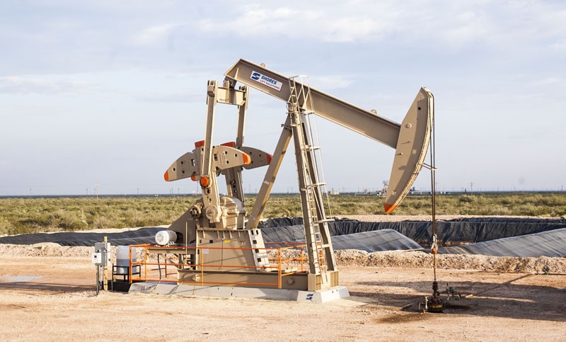
A pumpjack can be moving up and down all day while producing very little oil.
From the road, everything might look normal.
The motor is running. The walking beam is moving. The polished rod is travelling through its stroke.
But thousands of feet underground, something could be wrong.
The pump might be partially filled with gas. A valve could be leaking. The rod string might be experiencing excessive friction. The pump could be moving faster than the reservoir can supply fluid.
In some cases, the pumping unit continues operating even though the downhole pump is barely producing anything.
This is why oilfield operators and production engineers use dynamometer cards.
A dynamometer card provides information about the forces acting on a rod pumping system during each pumping cycle.
By studying the shape of the card, operators can identify potential problems without immediately pulling the pump out of the well.
Learning how to read a dynamometer card is one of the most useful troubleshooting skills for anyone working with pumpjacks, sucker rod pumps, or artificial lift systems.
What Is a Dynamometer Card?
A dynamometer card is a graph showing load compared with position during one complete pumping cycle.
As the pumping unit moves the polished rod up and down, the load on the rod changes.
A dynamometer measures these changes and displays them as a repeating pattern.
The shape of the pattern provides clues about what is happening inside the pumping system.
Operators often shorten the name to dyno card.
You may also hear someone call it a pump card.
However, there is an important difference between a surface dynamometer card and a calculated downhole pump card.
Understanding that difference is essential for accurate interpretation.
Why Do Oil Wells Need Dynamometer Testing?
The downhole pump can be thousands of feet below the surface.
The operator cannot directly see the plunger, standing valve, or traveling valve while the well is producing.
Instead, they have to rely on information available at the surface.
That can include:
Production volumes
Tubing pressure
Casing pressure
Motor current
Pumping speed
Stroke length
Fluid level
Polished rod load
These measurements are useful, but they do not always explain why a well is producing poorly.
Dynamometer testing adds valuable information.
It can help determine whether the pump is filling correctly, transferring fluid load normally, or experiencing mechanical problems.
A good dynamometer test can sometimes prevent an unnecessary service rig operation.
What Does a Dynamometer Card Actually Show?
Most dynamometer cards display two variables.
The horizontal axis represents rod or plunger position.
The vertical axis represents load.
As the pumping unit completes its cycle, the graph traces a closed pattern.
The upper and lower portions of the card represent different loading conditions during the stroke.
The transitions between them reveal how fluid load is transferred through the pumping system.
The exact shape depends on the type of card, pump design, rod string, well depth, fluid properties, and operating conditions.
A dynamometer card is not a direct photograph of the pump.
It is a representation of how the pump and rod string behave under load.
What Is Polished Rod Load?
The polished rod is the section of rod that passes through the stuffing box at the surface.
It connects the pumping unit to the sucker rod string extending down the well.
As the pumping unit lifts and lowers the rods, the force at the polished rod changes.
During the upstroke, the rod string normally carries additional load associated with lifting fluid.
During the downstroke, part of that fluid load is transferred away from the rod string.
However, the measured surface load includes more than fluid weight.
It also reflects rod weight, acceleration, friction, vibration, and the elastic behavior of the rods.
That is why the surface card can look quite different from what is happening at the actual pump.
What Is a Surface Dynamometer Card?
A surface dynamometer card shows measured polished rod load against polished rod position.
This is the card obtained from measurements at the pumping unit.
It provides information about the entire pumping system.
A surface card can help identify:
Abnormal rod loading
Excessive friction
Mechanical vibration
Possible rod failures
Unusual pumping behavior
Changes in fluid loading
Potential mechanical restrictions
But there is an important limitation.
A long sucker rod string behaves like an elastic spring.
It stretches, contracts, and vibrates as the pumping unit operates.
These effects distort the surface measurements.
A healthy well therefore does not necessarily produce a perfectly rectangular surface card.
What Is a Downhole Pump Card?
A downhole pump card is calculated from surface dynamometer measurements.
The analysis software uses a mathematical model of the rod string to estimate load and displacement at the downhole plunger.
The model accounts for factors such as rod elasticity, motion, weight, friction, and wave propagation.
The objective is to remove much of the distortion caused by the long rod string.
The calculated card provides a clearer representation of the pump’s actual operating behavior.
When operators discuss common shapes associated with fluid pound, gas interference, or valve leakage, they are often referring to downhole pump cards.
However, these calculated cards depend on accurate equipment information.
Incorrect rod dimensions, pump depth, or other model inputs can produce misleading results.
What Does a Healthy Downhole Pump Card Look Like?
An ideal downhole card from a properly filled rod pump is approximately rectangular.
The upper portion represents the fluid load being carried during the upstroke.
The lower portion represents reduced load during the downstroke.
The relatively steep sides represent load transfer as the pump valves change their operating state.
Real pump cards rarely form perfect rectangles.
Friction, gas, tubing movement, fluid properties, and valve behavior can change the shape.
An experienced operator therefore compares the card with the expected behavior of that particular well.
The objective is not to create a perfect rectangle.
The objective is to determine whether the pump is operating correctly.
How Does a Sucker Rod Pump Work?
Understanding the pumping cycle makes dynamometer interpretation much easier.
A conventional rod pump contains a plunger moving inside a barrel.
Two important valves control fluid movement.
The standing valve is located near the bottom of the pump assembly.
The traveling valve moves with the plunger.
During the upstroke, the traveling valve closes and the standing valve opens once the necessary pressure conditions are established.
The plunger lifts fluid in the tubing while additional fluid enters the pump barrel.
During the downstroke, the standing valve closes and the traveling valve opens once the appropriate pressure conditions develop.
Fluid passes through the traveling valve as the plunger moves downward.
The cycle repeats continuously.
The changing forces associated with this process create the load pattern shown on the dynamometer card.
What Does Pump Fillage Mean?
Pump fillage describes how completely the pump chamber fills during the pumping cycle.
When the pump receives enough liquid, it can use most of its available displacement.
When the chamber does not fill properly, part of the stroke becomes ineffective.
For example, a pump analysis system might estimate 60 percent fillage.
That suggests the pump is not obtaining a complete liquid fill.
However, fillage percentages should be interpreted carefully.
Gas compression, inaccurate pump parameters, fluid leakage, and other conditions can affect the calculation.
A displayed fillage number is a diagnostic estimate rather than a perfect measurement of actual production.
What Causes Low Pump Fillage?
Several problems can produce low fillage.
The reservoir may not supply enough liquid.
The pumping unit may be operating too fast.
Gas may be entering the pump.
The pump intake could be restricted.
The standing or traveling valve could be leaking.
The plunger and barrel might be worn.
The tubing may be moving excessively.
Low fillage does not automatically mean the well has run out of oil.
The cause matters because each problem requires a different response.
What Is Fluid Pound?
Fluid pound occurs when the pump chamber does not completely fill with liquid and the plunger experiences an abrupt load transfer during the downstroke.
Imagine a pump designed to move a certain volume every stroke.
The reservoir is delivering less fluid than the pump is attempting to displace.
The pump chamber becomes only partially filled.
During the downstroke, the plunger moves through the unfilled portion before encountering the liquid.
This can create a sudden change in loading.
Repeated fluid pound can contribute to rod fatigue, pump damage, and unnecessary mechanical stress.
The dynamometer card helps operators identify this condition.
What Does Fluid Pound Look Like on a Dynamometer Card?
On a calculated downhole card, fluid pound often appears as an abrupt unloading pattern during the downstroke.
The card may initially show normal fluid loading.
Then the load drops sharply partway through the stroke.
That sudden transition is an important clue.
The location of the transition can help indicate how much of the pump chamber is filling.
However, exact card shapes vary with the pumping system.
A fluid pound diagnosis should be supported by production information and fluid level measurements.
Why Does Fluid Pound Happen?
One of the most common causes is excessive pumping capacity compared with reservoir inflow.
Imagine a well capable of supplying 40 barrels of liquid per day.
The rod pump has a theoretical displacement of 90 barrels per day.
If pumping continues faster than fluid can enter the wellbore, the pump intake may eventually become starved.
The pump begins taking incomplete fills.
Fluid pound develops.
Increasing pumping speed will not make the reservoir supply more liquid.
It may simply increase the number of damaging pumping cycles.
What Is Pump Off?
Pump off describes a condition where the pumping system has removed enough liquid that reservoir inflow cannot maintain full pumping.
The pump may begin experiencing incomplete fillage.
This can occur when the pumping unit has more displacement capacity than the well’s current inflow rate.
Pump off is not necessarily evidence of pump failure.
Sometimes it means the pump is working faster than necessary.
A properly configured control system can help manage this condition.
What Is a Pump Off Controller?
A pump off controller monitors pumping behavior and changes operation when defined conditions are reached.
Some controllers use dynamometer information to recognize incomplete pump fillage.
They may stop the pumping unit temporarily or reduce speed where the equipment allows it.
After a suitable period, pumping resumes.
The objective is to allow the reservoir to replenish fluid while reducing unnecessary pumping.
This can improve equipment reliability, reduce mechanical loading, and lower energy consumption.
However, a pump off controller cannot create additional reservoir pressure or increase the well’s natural inflow capacity.
What Is Gas Interference in a Rod Pump?
Gas interference occurs when free gas enters the downhole pump and affects its ability to move liquid.
A rod pump is designed primarily for liquids.
Liquids are relatively incompressible.
Gas behaves differently.
During the downstroke, gas trapped inside the pump chamber compresses.
The traveling valve may not open until enough pressure develops inside the chamber.
This delays fluid transfer.
Part of the plunger movement is effectively spent compressing gas instead of moving liquid.
The result is reduced pump performance.
What Does Gas Interference Look Like on a Dyno Card?
Gas interference commonly produces a curved load transition on the downstroke of a calculated pump card.
Instead of unloading abruptly, the load changes more gradually as gas inside the chamber compresses.
The traveling valve opens after sufficient pressure develops.
This creates a recognizable pattern.
The shape may become more pronounced as the amount of gas entering the pump increases.
It can sometimes resemble incomplete pump fillage caused by insufficient liquid.
That is why a fluid level test is helpful.
What Is the Difference Between Gas Interference and Fluid Pound?
Both problems can reduce effective pumping.
But they are not identical.
Fluid pound involves an abrupt load transfer associated with incomplete liquid filling.
Gas interference involves the compression of gas inside the pump chamber.
Fluid pound often produces a sharper unloading pattern.
Gas interference often produces a smoother curved transition.
This difference can help operators distinguish the conditions.
However, both problems can exist in the same well.
A card may contain characteristics of both.
What Is Gas Lock?
Gas lock is a severe condition where gas inside the pump prevents normal valve operation.
The pump may continue moving while delivering very little liquid.
Because gas compresses and expands, the pressure differences needed to operate the standing and traveling valves may not develop properly.
A dynamometer card can show behavior consistent with gas lock.
But the diagnosis requires care.
Other mechanical problems can produce confusing card patterns.
The operator should review fluid level, casing pressure, gas production, pump conditions, and completion design before deciding what is wrong.
Can a Pump Have Gas Interference With Plenty of Liquid Above It?
Yes.
This is an important troubleshooting situation.
Imagine a well with a high fluid level above the pump intake.
The dynamometer card still shows poor fillage.
The reservoir is clearly supplying liquid.
But the pump may be handling enough free gas to reduce its effective displacement.
In this situation, slowing the pump may not address the fundamental issue.
The production team may need to evaluate gas separation, pump intake pressure, gas handling equipment, or completion design.
What Is a Standing Valve Leak?
The standing valve is designed to permit fluid to enter the pump while preventing unwanted reverse flow.
If it does not seal correctly, fluid can leak backward through the valve.
The pump may lose efficiency.
Common causes include wear, damaged valve components, debris, corrosion, and poor seating.
A standing valve leak changes the pressure and load behavior of the pump.
The calculated card may show abnormal load transfer during the pumping cycle.
Additional valve testing may help confirm the problem.
What Does a Standing Valve Leak Look Like?
Standing valve leakage can create an abnormal downstroke load pattern because fluid is able to escape through a valve that should be closed.
The expected load transfer may become distorted or extended.
The shape depends on how much leakage is occurring.
A minor leak can be difficult to recognize.
Severe leakage may significantly affect pump performance.
Operators should avoid diagnosing standing valve failure from a single card without considering other evidence.
What Is a Traveling Valve Leak?
The traveling valve moves with the pump plunger.
During the upstroke, it needs to seal properly so the plunger can lift fluid in the tubing.
If the valve leaks, fluid can slip backward.
The pump may continue stroking while producing less liquid.
Possible causes include damaged components, debris, wear, and improper seating.
The dynamometer card can show changes in how fluid load is transferred to the rod string.
What Does a Traveling Valve Leak Look Like?
A traveling valve leak can cause abnormal loading during the upstroke.
The pump may take longer to develop the expected fluid load because fluid is leaking through the valve.
The card may show a sloping or distorted loading transition.
The severity depends on leakage rate and other operating conditions.
Dedicated valve tests can provide additional evidence.
In some wells, traveling valve leakage and standing valve leakage can occur simultaneously.
This makes card interpretation more complicated.
What Does a Parted Rod Look Like on a Dynamometer Card?
A parted rod can cause one of the most dramatic changes in a dynamometer card.
When a sucker rod breaks or a coupling separates, the pumping unit may no longer be connected to the complete rod string and downhole pump.
The polished rod load can decrease significantly.
The card may become unusually narrow, flat, or distorted compared with previous measurements.
Production may decline sharply or stop.
A sudden major change in rod load combined with lost production should raise concern about a possible parted rod.
Continued operation can cause additional damage.
The well should be evaluated according to the company’s procedures.
Can a Dynamometer Card Identify a Tubing Leak?
It can provide clues.
A tubing leak allows produced fluid to escape from the tubing into the annulus.
The pump may still be moving liquid, but some of that liquid does not reach the surface production system.
The card can show reduced or abnormal fluid loading depending on the leak and pumping conditions.
However, tubing leaks are difficult to confirm using a dynamometer card alone.
Operators should compare the card with production history, tubing pressure, casing pressure, and other diagnostic information.
A pump valve leak can sometimes create similar symptoms.
What Is Tubing Movement?
Tubing movement occurs when the production tubing stretches or moves as loads change during the pumping cycle.
The pump barrel is normally connected to the tubing.
The plunger is connected to the rod string.
For the pump to move liquid effectively, the plunger needs to travel relative to the barrel.
If the tubing moves excessively, part of the surface stroke is lost.
The effective plunger stroke becomes shorter.
The dynamometer card may show unusual loading characteristics consistent with tubing movement.
This is one reason tubing anchoring matters.
What Does a Tubing Anchor Do?
A tubing anchor helps hold the tubing in place inside the casing.
It reduces unnecessary movement during rod pumping.
When tubing movement is excessive, pump displacement and efficiency can suffer.
Repeated tubing movement can also contribute to wear.
A poorly anchored tubing string can therefore create abnormal card shapes even when the pump itself is mechanically sound.
Before blaming the pump, operators should consider the tubing configuration.
What Is Pump Tagging?
Pump tagging occurs when the plunger or another moving component contacts a mechanical limit or component during its stroke.
This can happen when the pump is incorrectly spaced.
The contact creates an abnormal impact.
A dynamometer card may show a sharp spike or unusual distortion near the end of the stroke.
Repeated tagging can damage pump components and increase mechanical loading.
Proper pump spacing is important to prevent this condition.
Why Does Pump Spacing Matter?
Pump spacing determines the relationship between the plunger’s travel and the available movement inside the barrel.
The plunger needs sufficient clearance to operate without repeatedly striking mechanical components.
Incorrect spacing can reduce efficiency or create damaging contact.
Spacing should be evaluated whenever pump installation or rod work changes the system.
A dynamometer card can provide clues when something is wrong.
Can Friction Change the Dynamometer Card?
Yes.
Excessive friction changes the forces required to move the rod string.
During the upstroke, friction can increase the load.
During the downstroke, it can resist rod movement and affect the minimum measured load.
Possible causes include:
Rod contact with tubing
Paraffin deposits
Scale
Sand
Pump plunger friction
Mechanical misalignment
Stuffing box friction
Excessive friction can also increase energy consumption.
However, the card must be interpreted carefully because rod dynamics and fluid loading also influence its shape.
Can Sand Cause Abnormal Dyno Cards?
Yes.
Sand can wear the pump plunger and barrel.
It can interfere with standing and traveling valves.
It can increase friction.
It can cause components to stick.
In severe cases, sand can jam the pumping mechanism.
The resulting card may show irregular loads, sudden spikes, or changing shapes between strokes.
A sand related problem can be difficult to identify because several pump components may be affected simultaneously.
What Does a Worn Pump Look Like?
Over time, the plunger and barrel can wear.
Clearance may increase enough for fluid to slip past the plunger.
The pump continues moving but delivers less liquid.
A worn pump may show abnormal fluid load transfer or other changes in calculated pump behavior.
But the card alone may not clearly distinguish plunger wear from valve leakage.
Production history and additional testing help determine the likely cause.
Can Paraffin Affect a Dynamometer Card?
Yes.
Paraffin deposits can restrict movement or increase friction in the pumping system.
Deposits may accumulate on rods, inside tubing, or around components.
As friction increases, the load pattern may change.
Operators may also notice changes in motor load or production performance.
Paraffin should not automatically be blamed whenever a card becomes distorted.
Scale, sand, and mechanical wear can produce similar symptoms.
What Does a Pump Intake Restriction Look Like?
A pump intake restriction limits the amount of fluid entering the pump.
Even if liquid is available in the wellbore, the pump may not fill completely.
Sand, scale, debris, or other obstructions can restrict the intake.
The calculated card may show poor fillage.
This can resemble a well pumping faster than reservoir inflow.
A fluid level test becomes especially valuable.
If fluid level is high while fillage remains poor, an intake restriction or another pump problem deserves investigation.
Why Is Fluid Level Testing Important?
A dynamometer card shows how the pumping system behaves.
A fluid level test provides information about how much liquid is available in the wellbore.
Together, they are much more useful than either measurement alone.
Consider two wells showing poor pump fillage.
The first has a fluid level close to the pump intake.
That suggests the pump may be removing liquid faster than the reservoir supplies it.
The second has a high fluid level above the pump.
That suggests something else may be preventing effective pumping.
Possible causes include gas interference, valve leakage, intake restriction, or mechanical problems.
The card tells you what the pump is doing.
The fluid level helps explain why.
What Is Pump Intake Pressure?
Pump intake pressure is the pressure at the entrance to the downhole pump.
It influences the amount of fluid available and the amount of free gas that may enter.
When pump intake pressure falls, dissolved gas can come out of solution.
That can increase gas interference.
Pump intake pressure is influenced by fluid level, casing pressure, fluid density, and well conditions.
Engineers can estimate it using fluid level measurements and appropriate calculations.
This information helps determine whether the pumping system is operating under suitable conditions.
How Does Pumping Speed Affect a Dyno Card?
Increasing pumping speed changes the forces acting on the rod string.
Acceleration increases.
Rod dynamics change.
The pump attempts to displace more liquid per day.
If the reservoir cannot supply that additional liquid, pump fillage may decrease.
Fluid pound can become worse.
Higher speed can also increase mechanical wear.
In some wells, slowing the pump improves fillage and reduces equipment stress without significantly reducing actual fluid production.
The correct speed depends on the well.
Does Stroke Length Affect the Card?
Yes.
Stroke length determines how far the polished rod travels.
The effective downhole plunger stroke also depends on rod stretch, tubing movement, and other factors.
Increasing stroke length can increase theoretical pump displacement.
But it also changes loading and mechanical behavior.
A longer stroke is useful only when the pumping system and well conditions can support it.
Stroke length should be evaluated together with pumping speed, pump size, rod loading, and available fluid.
How Do You Calculate Theoretical Rod Pump Displacement?
A common field equation estimates theoretical rod pump displacement:
Barrels per day = 0.1166 × D² × S × N
Where:
D = Pump plunger diameter in inches
S = Effective plunger stroke in inches
N = Strokes per minute
This equation estimates the liquid volume the pump could move under ideal filling conditions.
It does not account for every real operating loss.
Gas interference, pump leakage, incomplete fillage, and other factors can reduce actual production.
A Simple Pump Displacement Example
Imagine a rod pump with these specifications.
Pump diameter: 1.75 inches
Effective plunger stroke: 100 inches
Pumping speed: 6 strokes per minute
The calculation is:
0.1166 × 1.75² × 100 × 6
The theoretical displacement is approximately 214 barrels per day.
Now imagine the well is only producing 110 barrels of liquid per day.
That difference does not automatically mean the pump needs to run faster.
The pump may lack fluid.
It may contain excessive gas.
The valves may be leaking.
The plunger may be worn.
The dynamometer card helps identify the reason for the difference.
What Is Volumetric Efficiency?
Volumetric efficiency compares actual liquid delivery with theoretical displacement.
Suppose the theoretical pump displacement is 200 barrels per day.
The measured liquid production is 140 barrels per day.
The simplified volumetric efficiency would be 70 percent.
However, actual efficiency calculations need reliable production measurements and correct pump information.
A low number can result from several different problems.
The objective is determining which problem is responsible.
Does a Bigger Dyno Card Mean More Oil Production?
Not necessarily.
The area inside a dynamometer card is related to the mechanical work represented by load and displacement.
It is not a direct measurement of oil production.
A pumping system can experience high loads while producing poorly.
Excessive friction can increase work without increasing liquid delivery.
The dynamometer card needs to be interpreted together with actual production measurements.
The goal is efficient fluid lifting, not simply generating a large card.
What Is Peak Polished Rod Load?
Peak polished rod load is the maximum load measured during the pumping cycle.
It is important because pumping equipment has design limits.
Excessive loading can contribute to rod failure and mechanical damage.
The pumping unit, rod string, and associated equipment must operate within their rated capabilities.
Dynamometer testing helps engineers evaluate these loads.
The maximum load should be considered alongside minimum load, pumping speed, stroke length, and the rod string design.
Why Does Rod Fatigue Matter?
Sucker rods experience repeated loading and unloading.
Imagine a well pumping six strokes per minute.
That equals 8,640 pumping cycles per day.
Over a year of continuous operation, the system completes more than three million cycles.
Every cycle contributes to repeated mechanical loading.
Fluid pound, corrosion, bending, friction, and excessive stress can accelerate fatigue.
This is why improving pump operation can extend equipment life.
Even relatively small reductions in damaging loads can become important over millions of cycles.
How Often Should You Run a Dynamometer Test?
There is no universal testing schedule.
Some wells have permanent dynamometer monitoring.
Others are tested periodically with portable equipment.
Testing becomes especially useful when something changes.
Examples include:
Sudden production decline
Unexpected motor loading
Abnormal pumping noise
Repeated rod failures
Changing fluid levels
Increasing gas interference
Pump replacement
Pumping speed changes
Suspected valve leakage
The best testing frequency depends on the well, available monitoring equipment, and company operating practices.
Can Dynamometer Cards Be Monitored Remotely?
Yes.
Modern rod pump controllers can transmit dynamometer information to remote monitoring systems.
Operators and engineers can review wells without visiting every location.
This allows companies to identify changing operating conditions across hundreds or thousands of wells.
A production engineer may notice falling pump fillage or changing rod load before the next scheduled field inspection.
However, remote measurements still need verification.
Bad sensors and incorrect configuration data can create misleading results.
Can Artificial Intelligence Read Dynamometer Cards?
Yes.
Automated analysis systems can recognize common patterns and identify possible pumping problems.
Software may flag conditions such as fluid pound, gas interference, valve leakage, and abnormal loading.
More advanced systems can compare current card patterns with historical behavior.
This can save time when monitoring large numbers of wells.
But automated diagnosis is not perfect.
Different problems can create similar patterns.
A software classification should be treated as a useful clue rather than absolute proof.
Experienced operators still need to understand the well.
Why Are Historical Dyno Cards So Valuable?
A single dynamometer card shows what is happening at one point in time.
Historical cards reveal how conditions have changed.
Imagine a well that produced normally for six months.
Its dynamometer card then begins showing increasing gas interference.
Pump fillage gradually decreases.
Production begins declining.
That trend provides much more information than one isolated card.
Comparing a well with its own historical performance is often more useful than comparing it with another well.
Every pumping system has different equipment and operating conditions.
Why Can Two Healthy Wells Have Different Cards?
Well depth affects the card.
Rod string design affects the card.
Pump size affects the card.
Tubing movement affects the card.
Pumping speed affects the card.
Fluid properties affect the card.
A deep well with a long rod string can have a surface card that looks very different from a shallow well.
Both may be operating correctly.
This is why experienced operators learn the normal characteristics of individual wells instead of relying entirely on memorized shapes.
What Information Should You Check Before Diagnosing a Dyno Card?
Start with the equipment.
Confirm pump size, rod string configuration, pump setting depth, stroke length, pumping speed, and tubing anchoring.
Then check the operating conditions.
Review production volumes, fluid level, tubing pressure, casing pressure, and recent operating changes.
Look for recent workovers or pump replacements.
Determine whether motor loading has changed.
Check whether the well has begun producing more gas or sand.
The dynamometer card should be interpreted within the complete operating picture.
A Practical Example of Fluid Pound
Imagine a well producing 30 barrels of liquid per day.
The rod pump has a theoretical displacement of 90 barrels per day.
A dynamometer test shows a sharp load drop during the downstroke.
A fluid level survey indicates liquid level is close to the pump intake.
These observations suggest the pump is attempting to move more liquid than the reservoir is currently supplying.
The production team may evaluate reducing pumping speed or using pump off control.
The objective is to match pumping capacity more closely with well inflow.
In this situation, a service rig may not be necessary.
A Practical Example of Gas Interference
Now imagine another well producing poorly.
The calculated pump card shows a long curved load transition.
The pattern suggests gas compression inside the pump chamber.
A fluid level survey shows substantial liquid above the pump intake.
This indicates that liquid availability may not be the main limitation.
The operator may investigate gas separation, pump intake conditions, casing pressure, or completion design.
Reducing pump speed might help in some circumstances, but it may not address the underlying gas handling problem.
A Practical Example of a Leaking Pump Valve
Consider an oil well that normally produces 75 barrels of liquid per day.
Production gradually falls to 40 barrels per day.
The pumping unit continues operating at the same speed.
A dynamometer test reveals abnormal load transfer.
Fluid level testing indicates plenty of liquid remains available.
Further valve testing suggests the traveling valve is leaking.
The pump is moving, but some fluid is slipping instead of reaching the surface.
In this case, increasing pumping speed may simply increase wear and energy consumption.
The information supports investigating pump condition rather than assuming insufficient reservoir inflow.
What Are Common Mistakes When Reading Dyno Cards?
One mistake is assuming every incomplete card means fluid pound.
Another is confusing gas interference with inadequate reservoir inflow.
Some operators diagnose pump valve leakage without supporting tests.
Others compare cards from completely different wells without considering equipment differences.
Incorrect rod string or pump parameters can also produce misleading calculated cards.
Another common mistake is focusing entirely on the shape while ignoring actual production.
A dyno card is a diagnostic tool.
It is not the final objective of the operation.
Should You Pull a Pump Based on One Bad Card?
Usually, one abnormal card should trigger further investigation rather than automatically justify a workover.
Pulling a rod pump can be expensive.
The well stops producing during the repair.
A service rig may be needed.
Rods and tubing may require inspection.
Equipment replacement adds cost.
Before making that decision, the production team should review all available evidence.
Sometimes the solution is changing pumping speed.
Sometimes it is adjusting pump off control.
Sometimes gas interference is the problem.
Other times the pump really is mechanically damaged.
A good dynamometer test helps avoid expensive guesses.
How Should a New Lease Operator Learn Dynamometer Interpretation?
Start with the pumping cycle.
Understand what the standing valve and traveling valve do.
Learn why fluid load changes between the upstroke and downstroke.
Then study the difference between surface and downhole cards.
Learn the common patterns associated with healthy operation, fluid pound, gas interference, leaking valves, and parted rods.
Compare those patterns with actual well measurements.
Ask experienced operators and production engineers to explain real cards from your field.
The fastest way to learn is by connecting each card with an actual operating condition.
Memorizing pictures is useful.
Understanding why those pictures develop is much more valuable.
A Practical Checklist for Reading a Dynamometer Card
When reviewing a new card, begin with these questions.
- Is the surface load within the expected operating range?
- Has the card changed significantly from previous tests?
- Is the downhole pump picking up and releasing fluid load normally?
- Does the calculated card suggest complete or incomplete fillage?
- Is there a sharp unloading pattern associated with fluid pound?
- Is there a curved load transition suggesting gas compression?
- Are there indications of valve leakage?
- Are there unusual load spikes suggesting mechanical contact?
- Does the fluid level support the suspected problem?
- Does the diagnosis explain the actual production behavior?
A strong interpretation should answer more than one of these questions.
It should provide a reasonable explanation of what is happening inside the well.
Frequently Asked Questions
What is a dynamometer card in oil and gas?
A dynamometer card is a graph showing how load changes with rod or pump position during a rod pumping cycle.
What is another name for a dynamometer card?
Operators commonly call it a dyno card or pump card.
What does a healthy downhole pump card look like?
An ideal properly filled downhole pump card is approximately rectangular, although actual card shapes vary with operating conditions.
What is the difference between a surface card and a downhole card?
A surface card uses measurements taken at the polished rod. A downhole card is calculated to represent the load and displacement at the pump.
What does fluid pound look like?
Fluid pound commonly creates a sharp unloading pattern during the downstroke of the calculated downhole card.
What causes fluid pound?
It often occurs when the pump does not receive enough liquid to fill its displacement volume.
What is gas interference?
Gas interference occurs when free gas enters the pump and compresses during the pumping cycle, reducing effective liquid displacement.
How can you tell gas interference from fluid pound?
Gas interference commonly produces a curved load transition, while severe fluid pound often produces a more abrupt transition.
What is gas lock?
Gas lock is a severe gas interference condition where gas prevents normal pump valve operation and useful liquid delivery.
Can a dynamometer card identify a bad standing valve?
It can show characteristics consistent with standing valve leakage, but additional testing may be required.
Can a dyno card show a traveling valve leak?
Yes. Traveling valve leakage can create abnormal load transfer during the pumping cycle.
What does a parted rod look like?
A parted rod can cause a major reduction in polished rod load and a dramatic change in card shape.
Can a dyno card identify tubing leaks?
It may provide clues, but tubing leaks generally require supporting pressure, production, or diagnostic testing.
Can sand damage a rod pump?
Yes. Sand can increase wear, interfere with valves, create friction, and cause mechanical restrictions.
Can paraffin affect the card?
Yes. Paraffin deposits can increase friction and restrict pump or rod movement.
What is pump fillage?
Pump fillage is an estimate of how completely the pump chamber fills during the pumping cycle.
Does low pump fillage mean the reservoir is depleted?
No. Gas interference, valve leakage, intake restrictions, and mechanical problems can also cause poor fillage.
Can a pump have low fillage with a high fluid level?
Yes. This may indicate gas interference, intake restriction, valve leakage, or another pump problem.
What is a pump off controller?
A pump off controller monitors pumping behavior and adjusts operation when the pump is no longer receiving sufficient liquid.
Can slowing a pump improve production efficiency?
Yes. When the pump is operating faster than available inflow, reducing speed can improve fillage and reduce mechanical stress.
Does pumping faster always produce more oil?
No. If reservoir inflow or pump condition is limiting production, increasing speed may provide no benefit.
Can you estimate barrels per day from pump displacement?
Yes. Theoretical pump displacement can be estimated from plunger diameter, effective stroke length, and pumping speed.
Does theoretical displacement equal actual production?
No. Actual production can be lower because of incomplete fillage, gas interference, leakage, and mechanical losses.
What is peak polished rod load?
It is the maximum load measured at the polished rod during a pumping cycle.
Why is rod fatigue important?
Sucker rods experience millions of repeated loading cycles. Excessive stress, fluid pound, corrosion, and friction can accelerate fatigue damage.
How often should you run a dynamometer test?
Testing frequency depends on the well and monitoring system. Additional testing is especially useful when production or mechanical behavior changes.
Can dyno cards be monitored remotely?
Yes. Modern rod pump controllers can transmit dynamometer information to remote monitoring systems.
Can software diagnose pump problems automatically?
Software can identify common patterns and suggest likely problems, but its interpretation should be checked against actual well conditions.
Can a pumpjack look normal while the downhole pump is failing?
Yes. A pumping unit can continue moving normally while the pump experiences poor fillage, gas interference, leaking valves, or mechanical damage.
What is the most important thing to remember when reading a dyno card?
Do not try to diagnose an entire oil well from the shape of one graph.
A dynamometer card is most useful when combined with fluid level testing, pressure measurements, production history, and knowledge of the pumping equipment.
The real objective is understanding what is happening underground well enough to make the correct operating decision.
A good operator does not simply recognize a card pattern.
They understand what created it, what it means for production, and what needs to happen next.